Wifi Jammer Circuit Diagram Programs
The communication between TV and remote control is IR (Infra Red) communication. So basically this circuit is a IR jammer circuit. As shown in below image the remote consists of an IR (Infrared) LED, which blinks every time a button is pressed.The TV consists of an IR receiver which receives these blinking pulses and decodes them for appropriate response. These IR pulses by remote control can not be detected by human eye. These pulses can be captured by a camera, as camera can pick up these pulses.As shown in figure, the IR communication established between TV and remote uses a wave length just above visible RED color.Circuit Components. +5v power supply. IR (Infra Red) LED (2 pieces). 555 Timer IC.
220Ω, 1KΩ and10KΩ resistors. 2N2222 transistor. 100KΩ preset or pot. 10nF or 22nF capacitor.
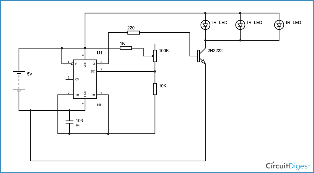
Circuit Diagram and ExplanationA TV Remote Control Signal Jammer Circuit Diagram is shown above. The communication established here is of frequency 32.5 KHz. That means the IR LED blinks at a rate of 32 KHz. Because this is too fast for a camera to pick, It picks up continuous turned on pulse.As shown in the below figure, the transmitter or remote blinks at 38 KHz whenever it need to send ONE or HIGH signal. The pulses when passed through decoders or filters at the receiving end (In this case, a TV) we get a complete ONE logic as shown in second graph of figure.So every time a button is pressed the remote sends out 38 KHz frequency IR pulses with regular intervals. These intervals differ with every button pressed. Because of these different intervals the receiver gets the correct information regarding the user requirement and acts accordingly.Now how we are going to stop the communication is the tricky part!
We are going to design a circuit which sends the pulses continuously. Because of these continuous pulses the receiver cannot pick up the intervals send by the TV remote control.Because of the continuous pulses by the TV remote signal jammer circuit the intervals of the remote are overlapped and the receiver reads ONE always. Simply speaking we are going to induce a lot of noise into the IR signal, for the receiver to completely read error all the time.So, here is designed to generate 38 KHz square wave. This square wave when connected to IR LED, the LED generates pulses at the same frequency. The potentiometer in the circuit must be adjusted to get the correct frequency.The timer output here is given to transistor to drive a couple or more IR LED’s.


Parallel Circuit Diagram
The pulses by jammer LED’s here overlap the communication intervals between remote and TV. So the TV reads always HIGH or ONE when the jammer is ON. Because of this, there will be no communication between the transmitter and receiver. This way we can block the TV remote communication.
Wifi Jammer Circuit Diagram Programs List
Apologies, I wasn't being mean (to you, Shock-Tech) - my comment was directed more at the author. I omitted a clarifying @andrew, given where my reply landed.I can't defend the idea of deliberately spoiling a limited shared resource. Sorry if that comes across as iTree hugging. But WiFi is an contended service already from people using it, never mind jamming it.Illegal or not (and it is), it's still not a nice thing to do.If you do do this, please make a really good job of it and get noticed for 'maliciously tampering with a communication system contrary to section umpty-mumble of the Terrorism Act' by some REALLY humourless government person.
You know what I mean?What next, instructables on how to successfully put noxious stuff in the town's drinking water? Or to chop through you're neighbour's broadband/fibre, for fun, naturally?:).